How to Install and Wire a Well Pump
Well Pump Installation Guide
Our previous article, Deep Well Pump Wiring Explained , describes the differences between 2-wire and 3-wire well pumps, and we highly recommend reading it before continuing on with the information below. It explains key differences between both types of well pumps, since each type will be installed differently.
This guide is a general overview of the steps that should be taken, and should not replace your owner's manual.
VIDEO
Before Installation Well pump installation can be dangerous when dealing with water and electricity, so extreme caution must be taken. Before getting started, look up your owner's manual
For new deep well installations, the well driller should have ensured a clear well free of any sand or debris left from drilling. Make sure the well is clear of any debris before installation or lowering your pump into the well.
Recommended Items for Installation Tools we recommend having on hand for installation include:
Pipe Wrenches Gloves and Safety Glasses Pipe Vices or Clamps Teflon Tape CSA/UL Approved Electrical Tape Tripod w/ Chain Hoist (for deep well pumps) Proper Gauge and Length of Submersible Wire Additional Check Valves may be needed depending on pump depth Torque Arrestor Other Misc. Tools
Understanding Well Pump Wiring Diagrams Learning how to read well pump wiring diagrams is necessary to install a well pump properly. Deep submersible well pumps
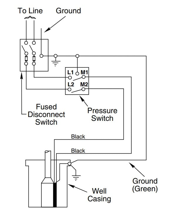
Two-Wire Well Pump Wiring Diagrams 2-wire well pump diagrams are slightly easier to understand, and are more straight-forward to wire. Black wires go to black wires, and the green wire (the ground) goes to the ground wire.
Fig. 1 (Above): 2 Wire Well Pump Wiring Diagram
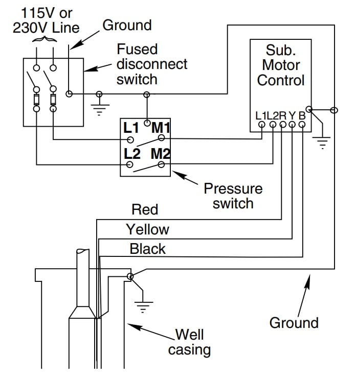
Three-Wire Well Pump Wiring Diagrams 3-wire well pump diagrams are more complicated and require a better understanding of electrical work. It's important that the wire colors go together.
Fig. 2 (Above): 3 Wire Well Pump Wiring Diagram
How to Wire a Well Pump The first step for installing a well pump is to familiarize yourself with the owner's manual and all the wiring steps you'll need to complete. You'll want to have all the tools you need handy, which should also be stated in the manual as well.
Step 1 - Disconnect All Power Easily the first step, all power should be turned off at the electrical panel and the pump's control box if applicable, and tested with a voltmeter to ensure no electricity is flowing to the installation location.
Step 2 - Ground the System Note that all wiring must meet National Electric Code and local electric code requirements for safety, so make sure to consult your owner's manual for information that may be unique to your deep well pump.
It's extremely important to properly ground the system to any metal plumbing, the control box (for 3-wire well pumps), and the motor frame using copper wire at least as thick as the other wires used to supply power to the pump motor. The owner's manual will include wiring charts to make sure the wire gauge (AWG) is correct, which will prevent the pump from overheating. Do not ground to a gas supply line.
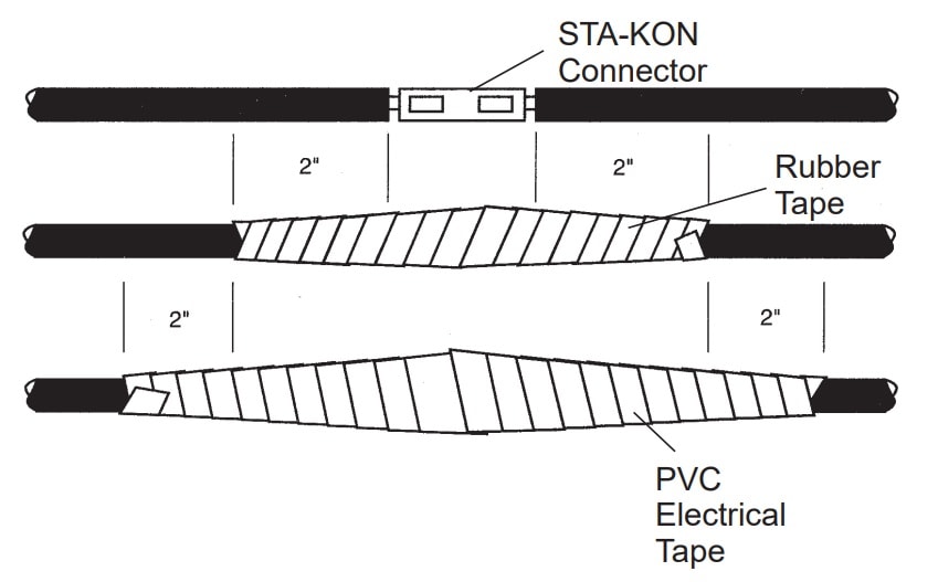
Step 3 - Make the Wiring Connections Splice the wires to the motor leads, matching the colors of the wire. In the case of 3-wire pumps, it will be red to red, yellow to yellow, and black to black. Only use copper wire. Make sure that any tape splicing that is done is spliced to be water-sealed. There are splice kits that can be purchased and make this step much easier than sourcing all materials separately. Make sure to use the proper tape.
Fig. 3 (Above): Tape Splicing Diagram
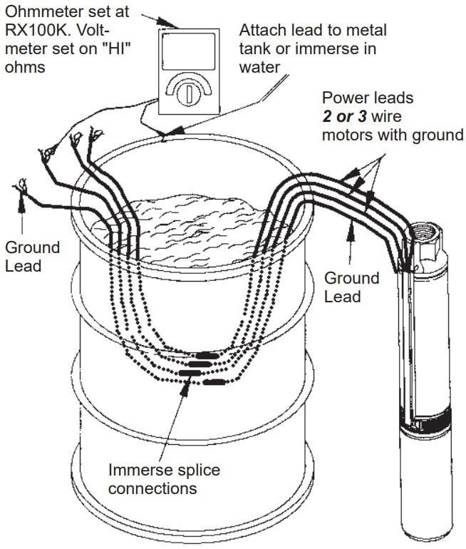
Step 4 - Test the Pump Before Installing To test the pump before installing, you'll need to connect it to the proper power supply. The frequency and voltage must match the motor nameplate frequency and voltage. Next, you'll need to properly attach the supply wire leads and attach the copper ground wire to the motor bracket. Remember to only use wires supplied by the manufacturer to ensure safety.
Now, submerge the spliced wires underwater to test the connection [see image]. Run the pump for no more than 30 seconds to see if it works properly (you never want to run a pump dry).
Fig. 4 (Above): Wire Water Test Example
Step 5 - Mount the Control Box Now that everything has been tested, it's time to install the control box. Again, see the owner's manual for specific instructions for your pump. Mount the control box in a permanent weather-proof location. Controls should never be exposed to moisture or excessive heat.
After the control box is mounted, make sure all controls are set to off and no electricity is turned on anywhere, before attempting to install the pump. Then, connect the box to the motor leads.
Step 6 - Install the Pump If you are using a standard air over water pressure tank, you need to drill two bleeder orifices about two feet apart so they will automatically charge the tank with air. If a pre-charged tank is being used or is replacing a traditional tank system, do not create new orifices, and remove old ones if necessary. To prevent dropping the pump, do not attempt to lower it into the well using the cord; instead, tie a safety rope long enough to reach the bottom of the well, permanently attached for later removal in the future.
For depths under 100 feet, use 100 PSI rated polyethylene plastic pipe. For depths under 220 feet, use 160 PSI rated polyethylene plastic pipe. For applications deeper than 220 feet, use galvanized steel pipe for the entire pipe length.
Initial Start-Up Precautions:
Never operate a pump when the discharge is completely closed; it can destroy itself. Never start the pump with the discharge completely open
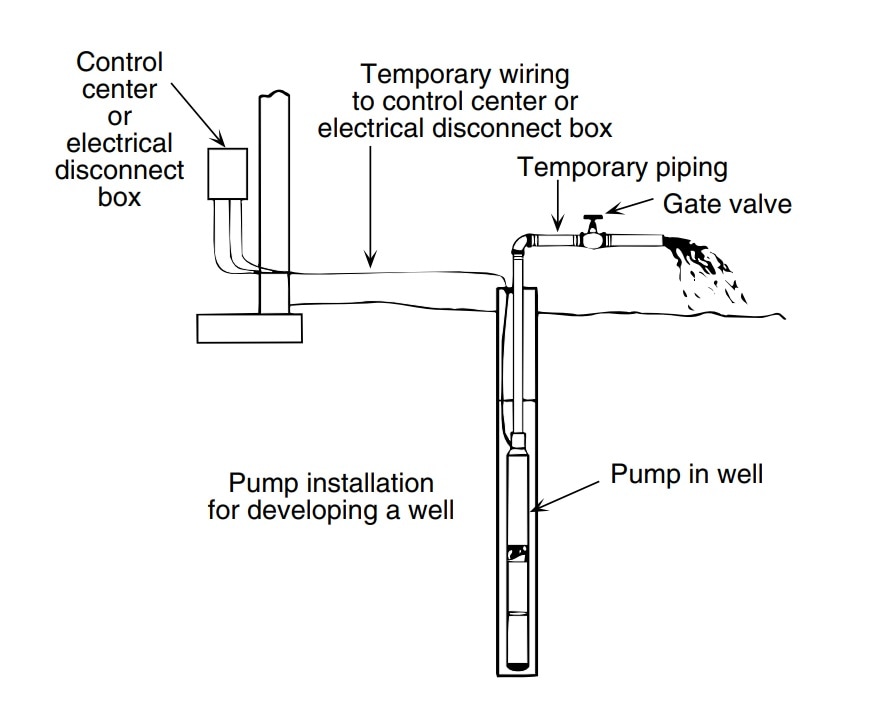
Step 7 - Clear Out the Well After the control box is set up and the motor leads have been connected, you'll need to attach a pipe elbow and a gate valve at the top of the piping temporarily in order to clean out the well. Set the gate valve on the discharge to be open one-third of the way. Then, start the pump and let the water run out until it is clear and free of dirt or sand. You can test this by filling up a clear cup with the water and looking for solids.
When water is running clear, turn off pump and repeat this process after opening the discharge to two-thirds open. After repeating this process, repeat it one more time after turning the pump off and opening the gate valve completely.
After this is done, remove the gate valve for permanent installation near the tank.
Fig. 5 (Above): Cleaning Out the Well Example Diagram
Step 8 - Attach to Water Tank Now it is time to attach the pump system to the water tank. Submersible tanks can cause high-pressure backups and even blow up, so be sure to install a pressure release valve that can pass full pump flow (follow local codes on this).
For this step, be sure to reference the owner's manual for detailed piping instructions and diagrams.
How to Prime a Well Pump If you've installed a deep well pump, the pump will already be primed since the impellers are underwater. If you've installed a shallow well pump, you'll need to take some extra steps in order to prime your well pump correctly before use. Simply click on the guide below to get started!
NEXT: How to Prime a Well Pump
Was this article helpful?
Yes
No
{"storeInfo":{"id":13,"name":"Power Equipment Direct","domain":"powerequipmentdirect.com","initials":"PED","url":"https:\/\/www.powerequipmentdirect.com","path":"\/var\/www\/vhosts\/ped.com\/"},"headerNavJSON":"{\"MainLinks\":[{\"URL\":\"\\\/outdoor\\\/air-compressors-direct.html\",\"displayText\":\"Air Compressors\",\"sectionLinks\":{\"columns\":\"6\",\"linkItems\":[{\"URL\":\"\\\/tools\\\/portable-air-compressors.html\",\"imageURL\":\"\\\/nav-image\\\/100\\\/compressor-13-1.jpg\",\"displayText\":\"Portable\"},{\"URL\":\"\\\/tools\\\/gas-air-compressors.html\",\"imageURL\":\"\\\/nav-image\\\/100\\\/compressor-13-2.jpg\",\"displayText\":\"Gas\"},{\"URL\":\"\\\/tools\\\/single-stage-air-compressors.html\",\"imageURL\":\"\\\/nav-image\\\/100\\\/compressor-13-3.jpg\",\"displayText\":\"Single-Stage\"},{\"URL\":\"\\\/tools\\\/two-stage-air-compressors.html\",\"imageURL\":\"\\\/nav-image\\\/100\\\/compressor-13-4.jpg\",\"displayText\":\"Two-Stage\"},{\"URL\":\"\\\/tools\\\/rotary-screw-air-compressors.html\",\"imageURL\":\"\\\/nav-image\\\/100\\\/compressor-13-5.jpg\",\"displayText\":\"Rotary Screw\"},{\"URL\":\"\\\/tools\\\/scroll-compressors.html\",\"imageURL\":\"\\\/nav-image\\\/100\\\/compressor-13-6.jpg\",\"displayText\":\"Scroll\"}]},\"subCategories\":[{\"URL\":null,\"type\":\"list\",\"title\":\"Featured Categories\",\"linkItems\":[{\"URL\":\"\\\/tools\\\/wheelbarrow-air-compressors.html\",\"displayText\":\"Wheelbarrow\"},{\"URL\":\"\\\/tools\\\/air-dryers.html\",\"displayText\":\"Air Dryers\"},{\"URL\":\"\\\/tools\\\/truck-mount-air-compressors.html\",\"displayText\":\"Truck Mount\"},{\"URL\":\"\\\/tools\\\/twin-stack-air-compressors.html\",\"displayText\":\"Twin Stack\"},{\"URL\":\"\\\/oil-free-air-compressors.html\",\"displayText\":\"Oil Free\"}]},{\"URL\":null,\"type\":\"list\",\"title\":\"Accessories\",\"linkItems\":[{\"URL\":\"\\\/tools\\\/impact-wrenches-pneumatic.html\",\"displayText\":\"Impact Wrenches\"},{\"URL\":\"\\\/tools\\\/air-treatment.html\",\"displayText\":\"Air Treatment\"},{\"URL\":\"\\\/tools\\\/air-tools.html\",\"displayText\":\"Air Tools\"},{\"URL\":\"\\\/tools\\\/air-compressor-accessories.html\",\"displayText\":\"All Accessories\"},{\"URL\":\"\\\/tools\\\/line-filters.html\",\"displayText\":\"Line Filters\"}]},{\"URL\":null,\"type\":\"list\",\"title\":\"Shop by Brand\",\"linkItems\":[{\"URL\":\"\\\/tools\\\/ingersoll-rand-air-compressors.html\",\"displayText\":\"Ingersoll Rand\"},{\"URL\":\"\\\/tools\\\/quincy-air-compressors.html\",\"displayText\":\"Quincy\"},{\"URL\":\"\\\/tools\\\/atlas-copco-compressors.html\",\"displayText\":\"Atlas Copco\"},{\"URL\":\"\\\/tools\\\/emax-air-compressors.html\",\"displayText\":\"EMAX\"},{\"URL\":\"\\\/tools\\\/industrial-air-compressors.html\",\"displayText\":\"Industrial Air\"}]},{\"URL\":\"\\\/stories\\\/156-How-to-Pick-the-Perfect-Air-Compressor.html\",\"type\":\"image\",\"title\":\"Buyer's Guide\",\"imageURL\":\"\\\/nav-article-image\\\/305\\\/social_img_156.jpg\",\"linkItems\":[],\"displayText\":\"The Ultimate Air Compressor Guide\"}]},{\"URL\":\"\\\/outdoor\\\/electric-generators-direct.html\",\"displayText\":\"Electric Generators\",\"sectionLinks\":{\"columns\":\"6\",\"linkItems\":[{\"URL\":\"\\\/power\\\/portable-generators.html\",\"imageURL\":\"\\\/nav-image\\\/100\\\/generator-13-1.jpg\",\"displayText\":\"Portable\"},{\"URL\":\"\\\/power\\\/home-standby-generators.html\",\"imageURL\":\"\\\/nav-image\\\/100\\\/generator-13-2.jpg\",\"displayText\":\"Home Standby\"},{\"URL\":\"\\\/power\\\/commercial-standby-generators.html\",\"imageURL\":\"\\\/nav-image\\\/100\\\/generator-13-3.jpg\",\"displayText\":\"Commercial\"},{\"URL\":\"\\\/power\\\/rv-generators.html\",\"imageURL\":\"\\\/nav-image\\\/100\\\/generator-13-4.jpg\",\"displayText\":\"RV\"},{\"URL\":\"\\\/power\\\/pto-generators.html\",\"imageURL\":\"\\\/nav-image\\\/100\\\/generator-13-5.jpg\",\"displayText\":\"PTO\"},{\"URL\":\"\\\/power\\\/transfer-switches.html\",\"imageURL\":\"\\\/nav-image\\\/100\\\/generator-13-6.jpg\",\"displayText\":\"Transfer Switches\"}]},\"subCategories\":[{\"URL\":null,\"type\":\"list\",\"title\":\"Featured Categories\",\"linkItems\":[{\"URL\":\"\\\/power\\\/whole-house-standby-generators.html\",\"displayText\":\"Whole House\"},{\"URL\":\"\\\/power\\\/inverter-generators.html\",\"displayText\":\"Inverter\"},{\"URL\":\"\\\/power\\\/electric-start-portable-generators.html\",\"displayText\":\"Electric Start\"},{\"URL\":\"\\\/power\\\/dual-fuel-generators.html\",\"displayText\":\"Dual Fuel\"},{\"URL\":\"\\\/power\\\/solar-generators.html\",\"displayText\":\"Solar Powered\"}]},{\"URL\":null,\"type\":\"list\",\"title\":\"Accessories\",\"linkItems\":[{\"URL\":\"\\\/power\\\/generator-power-cords.html\",\"displayText\":\"Power Cords\"},{\"URL\":\"\\\/power\\\/power-inlet-boxes.html\",\"displayText\":\"Power Inlet Boxes\"},{\"URL\":\"\\\/power\\\/generator-maintenance-kits.html\",\"displayText\":\"Maintenance Kits\"},{\"URL\":\"\\\/power\\\/portable-generator-covers.html\",\"displayText\":\"Covers & Tents\"},{\"URL\":\"\\\/outdoor\\\/electric-generator-accessories.html\",\"displayText\":\"All Accessories\"}]},{\"URL\":null,\"type\":\"list\",\"title\":\"Shop by Brand\",\"linkItems\":[{\"URL\":\"\\\/outdoor\\\/generac.html\",\"displayText\":\"Generac\"},{\"URL\":\"\\\/power\\\/honda-generators.html\",\"displayText\":\"Honda\"},{\"URL\":\"\\\/power\\\/kohler-generators.html\",\"displayText\":\"Kohler\"},{\"URL\":\"\\\/power\\\/briggs-and-stratton-generators.html\",\"displayText\":\"Briggs & Stratton\"},{\"URL\":\"\\\/power\\\/champion-generators.html\",\"displayText\":\"Champion\"}]},{\"URL\":\"\\\/stories\\\/305-How-to-Pick-the-Perfect-Electric-Generator.html\",\"type\":\"image\",\"title\":\"Buyer's Guide\",\"imageURL\":\"\\\/nav-article-image\\\/305\\\/social_img_305.jpg\",\"linkItems\":[],\"displayText\":\"What Kind of Generator do I Need for my House\"}]},{\"URL\":\"\\\/outdoor\\\/pressure-washers-direct.html\",\"displayText\":\"Pressure Washers\",\"sectionLinks\":{\"columns\":\"6\",\"linkItems\":[{\"URL\":\"\\\/power\\\/gas-pressure-washers.html\",\"imageURL\":\"\\\/nav-image\\\/100\\\/pressure-washer-13-1.jpg\",\"displayText\":\"Gas\"},{\"URL\":\"\\\/power\\\/electric-pressure-washers.html\",\"imageURL\":\"\\\/nav-image\\\/100\\\/pressure-washer-13-2.jpg\",\"displayText\":\"Electric\"},{\"URL\":\"\\\/power\\\/pressure-washer-pumps.html\",\"imageURL\":\"\\\/nav-image\\\/100\\\/pressure-washer-13-3.jpg\",\"displayText\":\"Pumps\"},{\"URL\":\"\\\/power\\\/pressure-washer-hoses.html\",\"imageURL\":\"\\\/nav-image\\\/100\\\/pressure-washer-13-4.jpg\",\"displayText\":\"Hoses\"},{\"URL\":\"\\\/power\\\/jetters.html\",\"imageURL\":\"\\\/nav-image\\\/100\\\/pressure-washer-13-5.jpg\",\"displayText\":\"Jetters\"},{\"URL\":\"\\\/power\\\/commercial-pressure-washers.html\",\"imageURL\":\"\\\/nav-image\\\/100\\\/pressure-washer-13-6.jpg\",\"displayText\":\"Commercial\"}]},\"subCategories\":[{\"URL\":null,\"type\":\"list\",\"title\":\"Featured Categories\",\"linkItems\":[{\"URL\":\"\\\/power\\\/commercial-start-your-own-business-kits.html\",\"displayText\":\"Business Kits\"},{\"URL\":\"\\\/power\\\/commercial-truck-mount-pressure-washers.html\",\"displayText\":\"Truck Mount\"},{\"URL\":\"\\\/power\\\/commercial-wall-mount-pressure-washers.html\",\"displayText\":\"Wall Mount\"},{\"URL\":\"\\\/power\\\/hot-water-pressure-washers.html\",\"displayText\":\"Hot Water\"},{\"URL\":\"\\\/power\\\/gas-pressure-washers.html\",\"displayText\":\"Gas Powered\"}]},{\"URL\":null,\"type\":\"list\",\"title\":\"Accessories\",\"linkItems\":[{\"URL\":\"\\\/power\\\/surface-cleaners.html\",\"displayText\":\"Surface Cleaners\"},{\"URL\":\"\\\/power\\\/pressure-washer-telescoping-wands.html\",\"displayText\":\"Telescoping Wands\"},{\"URL\":\"\\\/power\\\/pressure-washer-spray-rollers.html\",\"displayText\":\"Spray Guns\"},{\"URL\":\"\\\/power\\\/pressure-washer-soap-nozzles.html\",\"displayText\":\"Nozzles\"},{\"URL\":\"\\\/power\\\/pressure-washer-attachment.html\",\"displayText\":\"All Accessories\"}]},{\"URL\":null,\"type\":\"list\",\"title\":\"Shop by Brand\",\"linkItems\":[{\"URL\":\"\\\/power\\\/simpson-pressure-washers.html\",\"displayText\":\"Simpson\"},{\"URL\":\"\\\/power\\\/pressure-pro-pressure-washers.html\",\"displayText\":\"Pressure-Pro\"},{\"URL\":\"\\\/power\\\/be-pressure-washers.html\",\"displayText\":\"BE\"},{\"URL\":\"\\\/power\\\/general-pump-pressure-washers.html\",\"displayText\":\"General Pump\"},{\"URL\":\"\\\/power\\\/easy-kleen-pressure-washers.html\",\"displayText\":\"Easy-Kleen\"}]},{\"URL\":\"\\\/stories\\\/343-How-to-Pick-the-Perfect-Pressure-Washer.html\",\"type\":\"image\",\"title\":\"Buyer's Guide\",\"imageURL\":\"\\\/nav-article-image\\\/305\\\/social_img_343.jpg\",\"linkItems\":[],\"displayText\":\"Pressure Washer Buyer's Guide\"}]},{\"URL\":\"\\\/outdoor\\\/sump-pumps-direct.html\",\"displayText\":\"Sump Pumps\",\"sectionLinks\":{\"columns\":\"6\",\"linkItems\":[{\"URL\":\"\\\/pumps\\\/primary-sump-pumps.html\",\"imageURL\":\"\\\/nav-image\\\/100\\\/primary_56776234fd355c5a6971fc4fe3b1a559.jpg\",\"displayText\":\"Primary\"},{\"URL\":\"\\\/pumps\\\/combination-sump-pump-systems.html\",\"imageURL\":\"\\\/nav-image\\\/100\\\/Combination_d1accf365a102db5033f2a6f6bd37f98.jpg\",\"displayText\":\"Combination\"},{\"URL\":\"\\\/pumps\\\/battery-backup-sump-pumps.html\",\"imageURL\":\"\\\/nav-image\\\/100\\\/Battery Backup_57ed4885b879f30ee0134fc50cf51b8f.jpg\",\"displayText\":\"Battery Backup\"},{\"URL\":\"\\\/pumps\\\/sewage-pumps.html\",\"imageURL\":\"\\\/nav-image\\\/100\\\/Sewage_7c435fa06b22cee7de46cb44ef798ee7.jpg\",\"displayText\":\"Sewage\"},{\"URL\":\"\\\/pumps\\\/grinder-pumps.html\",\"imageURL\":\"\\\/nav-image\\\/100\\\/Grinder_74abf9c1c797dbdc6bdaedc569127969.jpg\",\"displayText\":\"Grinder\"},{\"URL\":\"\\\/pumps\\\/specialty-sump-pumps.html\",\"imageURL\":\"\\\/nav-image\\\/100\\\/Specialty_2e682b88db34300c4023504e9e23c845.jpg\",\"displayText\":\"Specialty\"}]},\"subCategories\":[{\"URL\":null,\"type\":\"list\",\"title\":\"Featured Categories\",\"linkItems\":[{\"URL\":\"\\\/pumps\\\/primary-submersible-sump-pumps.html\",\"displayText\":\"Primary Submersible\"},{\"URL\":\"\\\/pumps\\\/sewage-pump-systems.html\",\"displayText\":\"Sewage Systems\"},{\"URL\":\"\\\/pumps\\\/effluent-pumps.html\",\"displayText\":\"Effluent\"},{\"URL\":\"\\\/pumps\\\/laundry-drain-pump-systems.html\",\"displayText\":\"Drain\"},{\"URL\":\"\\\/pumps\\\/primary-pedestal-sump-pumps.html\",\"displayText\":\"Primary Pedestal\"}]},{\"URL\":null,\"type\":\"list\",\"title\":\"Accessories\",\"linkItems\":[{\"URL\":\"\\\/pumps\\\/sump-pump-batteries.html\",\"displayText\":\"Batteries\"},{\"URL\":\"\\\/pumps\\\/sump-pump-switches.html\",\"displayText\":\"Switches\"},{\"URL\":\"\\\/pumps\\\/sump-pump-and-sewage-pump-control-boxes.html\",\"displayText\":\"Control Boxes\"},{\"URL\":\"\\\/pumps\\\/auxiliary-power-systems.html\",\"displayText\":\"Auxiliary Power System\"},{\"URL\":\"\\\/pumps\\\/sump-pump-accessory.html\",\"displayText\":\"All Accessories\"}]},{\"URL\":null,\"type\":\"list\",\"title\":\"Shop by Brand\",\"linkItems\":[{\"URL\":\"\\\/pumps\\\/liberty-pumps.html\",\"displayText\":\"Liberty Pumps\"},{\"URL\":\"\\\/pumps\\\/zoeller-pumps.html\",\"displayText\":\"Zoeller\"},{\"URL\":\"\\\/pumps\\\/phcc-pro-series-pumps.html\",\"displayText\":\"Pro Series\"},{\"URL\":\"\\\/pumps\\\/bur-cam-pumps.html\",\"displayText\":\"Burcam\"},{\"URL\":\"\\\/pumps\\\/ion-pumps.html\",\"displayText\":\"iON Products\"}]},{\"URL\":\"\\\/stories\\\/784-Best-Selling-and-Top-Rated-Sump-Pumps.html\",\"type\":\"image\",\"title\":\"Buyer's Guide\",\"imageURL\":\"\\\/nav-article-image\\\/305\\\/social_img_784.jpg\",\"linkItems\":[],\"displayText\":\"The Best Sump Pumps of 2024\"}]},{\"URL\":\"\\\/outdoor\\\/water-pumps-direct.html\",\"displayText\":\"Water Pumps\",\"sectionLinks\":{\"columns\":\"6\",\"linkItems\":[{\"URL\":\"\\\/pumps\\\/electric-water-pumps.html\",\"imageURL\":\"\\\/nav-image\\\/100\\\/water-pump-13-1.jpg\",\"displayText\":\"Electric\"},{\"URL\":\"\\\/pumps\\\/gas-powered-water-pumps.html\",\"imageURL\":\"\\\/nav-image\\\/100\\\/water-pump-13-2.jpg\",\"displayText\":\"Gas\"},{\"URL\":\"\\\/pumps\\\/well-pumps.html\",\"imageURL\":\"\\\/nav-image\\\/100\\\/water-pump-13-3.jpg\",\"displayText\":\"Well\"},{\"URL\":\"\\\/pumps\\\/dewatering-pumps.html\",\"imageURL\":\"\\\/nav-image\\\/100\\\/water-pump-13-5.jpg\",\"displayText\":\"Dewatering\"},{\"URL\":\"\\\/pumps\\\/trash-pumps.html\",\"imageURL\":\"\\\/nav-image\\\/100\\\/water-pump-13-6.jpg\",\"displayText\":\"Trash\"},{\"URL\":\"\\\/pumps\\\/sprinkler-pumps.html\",\"imageURL\":\"\\\/nav-image\\\/100\\\/sprinkler_503ba4a09158d65372eb111aeb27c0b3.jpg\",\"displayText\":\"Sprinkler\"}]},\"subCategories\":[{\"URL\":null,\"type\":\"list\",\"title\":\"Featured Categories\",\"linkItems\":[{\"URL\":\"\\\/pumps\\\/utility-pumps.html\",\"displayText\":\"Utility\"},{\"URL\":\"\\\/pumps\\\/chemical-pumps.html\",\"displayText\":\"Chemical\"},{\"URL\":\"\\\/pumps\\\/transfer-pumps.html\",\"displayText\":\"Transfer\"},{\"URL\":\"\\\/pumps\\\/diesel-powered-pumps.html\",\"displayText\":\"Diesel\"},{\"URL\":\"\\\/pumps\\\/miscellaneous-power-types.html\",\"displayText\":\"Specialty Power\"}]},{\"URL\":null,\"type\":\"list\",\"title\":\"Accessories\",\"linkItems\":[{\"URL\":\"\\\/pumps\\\/water-pump-discharge-hoses.html\",\"displayText\":\"Hoses\"},{\"URL\":\"\\\/pumps\\\/well-pump-control-boxes.html\",\"displayText\":\"Control Boxes\"},{\"URL\":\"\\\/pumps\\\/float-switches.html\",\"displayText\":\"Switches\"},{\"URL\":\"\\\/pumps\\\/water-pump-quick-couplings.html\",\"displayText\":\"Quick Couplings\"},{\"URL\":\"\\\/pumps\\\/water-pump-accessory.html\",\"displayText\":\"All Accessories\"}]},{\"URL\":null,\"type\":\"list\",\"title\":\"Shop by Brand\",\"linkItems\":[{\"URL\":\"\\\/pumps\\\/honda-water-pumps.html\",\"displayText\":\"Honda\"},{\"URL\":\"\\\/pumps\\\/flotec-water-pumps.html\",\"displayText\":\"Flotec\"},{\"URL\":\"\\\/pumps\\\/multiquip-water-pumps.html\",\"displayText\":\"Multiquip\"},{\"URL\":\"\\\/pumps\\\/tsurumi-water-pumps.html\",\"displayText\":\"Tsurumi Pump\"},{\"URL\":\"\\\/pumps\\\/red-lion-water-pumps.html\",\"displayText\":\"Red Lion\"}]},{\"URL\":\"\\\/stories\\\/281-How-to-Pick-the-Perfect-Water-Pump.html\",\"type\":\"image\",\"title\":\"Buyer's Guide\",\"imageURL\":\"\\\/nav-article-image\\\/305\\\/social_img_281.jpg\",\"linkItems\":[],\"displayText\":\"Water Pump Buyer's Guide\"}]},{\"URL\":null,\"displayText\":\"More\",\"sectionLinks\":{\"columns\":\"6\",\"linkItems\":[{\"URL\":\"https:\\\/\\\/www.ecomfort.com\\\/cooling\\\/ductless-mini-split-systems.html\",\"imageURL\":\"\\\/nav-image\\\/100\\\/ls120hev2_99293_600_566a8b8447567d17e07268f4f6d958a4.jpg\",\"displayText\":\"Mini Splits\"},{\"URL\":\"https:\\\/\\\/www.ecomfort.com\\\/cooling\\\/room-air-conditioners.html\",\"imageURL\":\"\\\/nav-image\\\/100\\\/mass_140040_cd360daf61cd951f5221c80ff4941449.png\",\"displayText\":\"Room ACs and PTACs\"},{\"URL\":\"\\\/power\\\/jetters.html\",\"imageURL\":\"\\\/nav-image\\\/100\\\/JD4040HG_12827_600_72dcd6c01efe128e37c54c597bd42b59.jpg\",\"displayText\":\"Jetters\"},{\"URL\":\"\\\/outdoor\\\/paint-sprayers-direct.html\",\"imageURL\":\"\\\/nav-image\\\/100\\\/805-000_76239_1000_21900ab5e97ce4d1a242111121a10762_59ff9bc3ee387c5dd0131fb6cb89b426.jpg\",\"displayText\":\"Paint Sprayers\"}]},\"subCategories\":[{\"URL\":null,\"type\":\"list\",\"title\":\"Home Equipment\",\"linkItems\":[{\"URL\":\"https:\\\/\\\/www.ecomfort.com\\\/cooling\\\/central-air-conditioners.html\",\"displayText\":\"Air Conditioners\"},{\"URL\":\"https:\\\/\\\/www.ecomfort.com\\\/heating\\\/boilers.html\",\"displayText\":\"Boilers\"},{\"URL\":\"https:\\\/\\\/www.ecomfort.com\\\/heating\\\/furnaces.html\",\"displayText\":\"Furnaces\"},{\"URL\":\"https:\\\/\\\/www.ecomfort.com\\\/cooling\\\/ductless-mini-split-systems.html\",\"displayText\":\"Mini Splits\"},{\"URL\":\"https:\\\/\\\/www.ecomfort.com\\\/water-heaters\\\/water-heaters.html\",\"displayText\":\"Water Heaters\"}]},{\"URL\":null,\"type\":\"list\",\"title\":\"Home Appliances\",\"linkItems\":[{\"URL\":\"https:\\\/\\\/www.ecomfort.com\\\/cooling\\\/beverage-coolers.html\",\"displayText\":\"Beverage Coolers\"},{\"URL\":\"https:\\\/\\\/www.ecomfort.com\\\/appliances\\\/garbage-disposals.html\",\"displayText\":\"Garbage Disposals\"},{\"URL\":\"https:\\\/\\\/www.ecomfort.com\\\/cooling\\\/kegerators.html\",\"displayText\":\"Kegerators\"},{\"URL\":\"https:\\\/\\\/www.ecomfort.com\\\/cooling\\\/room-air-conditioners.html\",\"displayText\":\"Room Air Conditioners\"},{\"URL\":\"https:\\\/\\\/www.ecomfort.com\\\/cooling\\\/wine-coolers.html\",\"displayText\":\"Wine Coolers\"}]},{\"URL\":null,\"type\":\"list\",\"title\":\"Tools\",\"linkItems\":[{\"URL\":\"\\\/tools\\\/air-tools.html\",\"displayText\":\"Air Tools\"},{\"URL\":\"https:\\\/\\\/www.ecomfort.com\\\/cooling\\\/tools.html\",\"displayText\":\"HVAC Tools\"},{\"URL\":\"\\\/outdoor\\\/paint-sprayers-direct.html\",\"displayText\":\"Paint Sprayers\"}]},{\"URL\":null,\"type\":\"list\",\"title\":\"Commercial Equipment\",\"linkItems\":[{\"URL\":\"\\\/tools\\\/demolition-tools.html\",\"displayText\":\"Demolition Tools\"},{\"URL\":\"\\\/power\\\/jetters.html\",\"displayText\":\"Jetters\"},{\"URL\":\"\\\/power\\\/light-towers.html\",\"displayText\":\"Light Towers\"}]}]},{\"URL\":\"\\\/how-to-library.php\",\"displayText\":\"How-to-Library\",\"sectionLinks\":{\"columns\":\"6\",\"linkItems\":[{\"URL\":null,\"imageURL\":null,\"displayText\":\"\"}]},\"subCategories\":[]},{\"URL\":\"\\\/outdoor\\\/power-equipment-on-sale.html\",\"displayText\":\"Weekly Specials\",\"sectionLinks\":{\"columns\":\"6\",\"linkItems\":[{\"URL\":null,\"imageURL\":null,\"displayText\":\"\"}]},\"subCategories\":[]},{\"URL\":\"https:\\\/\\\/www.ecomfort.com\\\/\",\"displayText\":\"HVAC at eComfort.com\",\"sectionLinks\":{\"columns\":\"6\",\"linkItems\":[{\"URL\":null,\"imageURL\":null,\"displayText\":\"\"}]},\"subCategories\":[]}],\"USP\":[{\"id\":\"479\",\"URL\":\"\\\/stories\\\/479-How-To-Get-Free-Shipping-On-Power-Equipment.html\",\"className\":\"icon-nav-usp-shipping\",\"displayText\":\"Free Shipping\"},{\"id\":\"359\",\"URL\":\"\\\/stories\\\/359-Serious-Power-Equipment-Worth-Bragging-About.html\",\"className\":\"icon-nav-usp-reviews\",\"displayText\":\"Expert Recommendations\"},{\"id\":\"1261\",\"URL\":\"\\\/stories\\\/1261-Power-Equipment-Direct-Credit-Made-Simple.html\",\"className\":\"icon-nav-usp-financing\",\"displayText\":\"Financing\"},{\"id\":\"1991\",\"URL\":\"\\\/stories\\\/1991-New-Customer-Referral-Program.html\",\"className\":\"icon-referral\",\"displayText\":\"Customer Referral Program\"}]}","siteLinkJSON":"{\"Resources\":{\"How to Library\":{\"href\":\"how-to-library.php\",\"title\":\"Power Equipment Direct How-To Library\"},\"Product Reviews\":{\"href\":\"reviews.php\",\"title\":\"Customer Reviews on Power Equipment Direct Products\"},\"Recommendations\":{\"href\":\"stories\\\/359-Serious-Power-Equipment-Worth-Bragging-About.html\",\"title\":\"Product Recommendations\"},\"Weekly Specials\":{\"href\":\"outdoor\\\/power-equipment-on-sale.html\",\"title\":\"Weekly Power Equipment Direct Specials\"},\"Manuals\":{\"href\":\"stories\\\/399-How-to-Access-Old-Power-Equipment-Manuals.html\",\"title\":\"Manual Lookup\"},\"Service Centers\":{\"href\":\"stories\\\/414-How-to-Find-a-Service-Center-For-Your-Power-Equipment.html\",\"title\":\"Service Centers\"},\"Technical Support\":{\"href\":\"stories\\\/425-How-to-Find-Tech-Support-For-Your-Power-Equipment.html\",\"title\":\"Technical Support\"}},\"Account\":{\"My Account\":{\"href\":\"account.php\",\"title\":\"Login to My Account\"},\"Email Preferences\":{\"href\":\"https:\\\/\\\/www.powerequipmentdirect.com\\\/newsletter_removal.php\",\"title\":\"Email Preferences\"},\"Manufacturer Login\":{\"href\":\"https:\\\/\\\/www.powerequipmentdirect.com\\\/partnerships\\\/login.php\",\"title\":\"Manufacturer Login\"}},\"Customer Service\":{\"Help Center\":{\"href\":\"contact_us.php\",\"title\":\"Help Center\"},\"Return Policy\":{\"href\":\"returns.php\",\"title\":\"Return Policy\"},\"Shipping Policy\":{\"href\":\"stories\\\/515-How-to-Easily-Unload-Power-Equipment.html\",\"title\":\"Shipping Policy\"},\"Product Recalls\":{\"href\":\"stories\\\/1175-Product-Recalls-for-Power-Equipment.html\",\"title\":\"Product Recalls\"},\"Track Order\":{\"href\":\"ordertracking.php\",\"title\":\"Order Tracking\"},\"Accessibility\":{\"href\":\"stories\\\/1769-Our-Commitment-to-Accessibility.html\",\"title\":\"Accessibility\"},\"Do Not Sell or
We Make Buying Technical Products Simple